In this article, I look at using the Raspberry Pi GPIO PWM for DC motor control. Through Python programming, I look at how to interface with a typical H-Bridge DC motor driver. Furthermore, H-Bridge diver code examples with wire connection illustrations are included.
There is a lot that goes on in code between R/C controller input and H-Bridge DC motor driver output. This is especially true where the robot vehicle is a skid steer type. So, getting a bit of understanding of how the hardware works first will help create the rest of the robot control software. Furthermore, it is worth noting to keep hardware driver software code routines separate from robot control logic routines. This will help keep the Python code elements of the robot control software modular.
I have already covered R/C controller input using a game controller here. Now, I take a look at how to drive a typical H-Bridge module, connected to a Raspberry, with GPIO PWM.
GPIO PWM
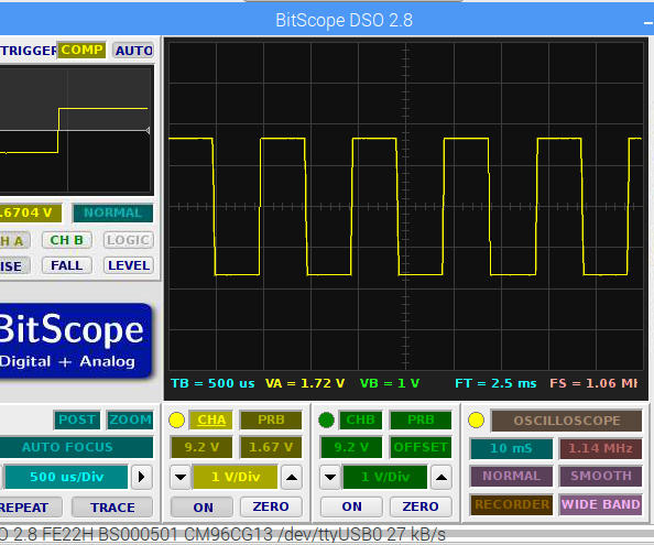
I admit at this point I do not know how the GPIO PWM is implemented on the Raspberry Pi. But I believe the PWM is software driven using a shared clock source and might involve DMA channels. In any case, from my own tests, I am confident that I can get some decent DC motor control by attaching an H-Bridge module directly to the Raspberry Pi. Then use GPIO PWM through the GPIO Zero API. I think this is an ideal approach for makers beginning to build their own R/C robot project.
GPIO PWM Python 3 API
First, I will take a look at the GPIO Zero API as a quick brief on how to get PWM working. And while there are a few other ways to get PWM working on the Raspberry Pi, the Python class I will be focusing on is PWMOutputDevice. However, GPIO Zero API is well documented and information on all available classes is here. Then I take a look at how the GPIO PWM might interface with an H-Bridge module.
From gpiozero import PWMOutputDevice
leftWheels = PWMOutputDevice(21)
leftWheels.frequency = 1000
leftWheels.value = 0.50
The above python code shows the initial PWM setup. While using (BCM) pin numbering, I initialize a new object I call leftWheels with a Raspberry Pi GPIO pin Number. Then I use property setters frequency and value to set the initial PWM frequency and duty cycle. Then during robot control operation, the duty cycle is the only value I will change for PWM robot speed control.
The duty cycle range is between 0.0 and 1.0 inclusive. So consequently a re-map function may be required to convert controller output value ranges to PWM duty cycle ranges. Adjusting the PWM duty cycle, for instance, will allow variable RPM control of DC motors.
Also, check for additional initialisation settings and other class properties and methods at the following link.
- API – Output Devices — GPIO Zero Documentation
GPIO PWM Python 3 Code Examples
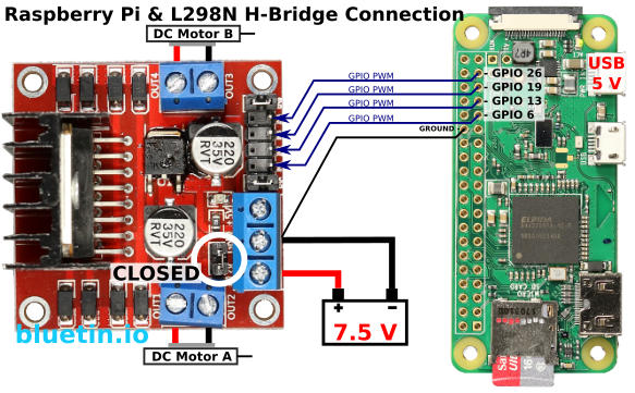
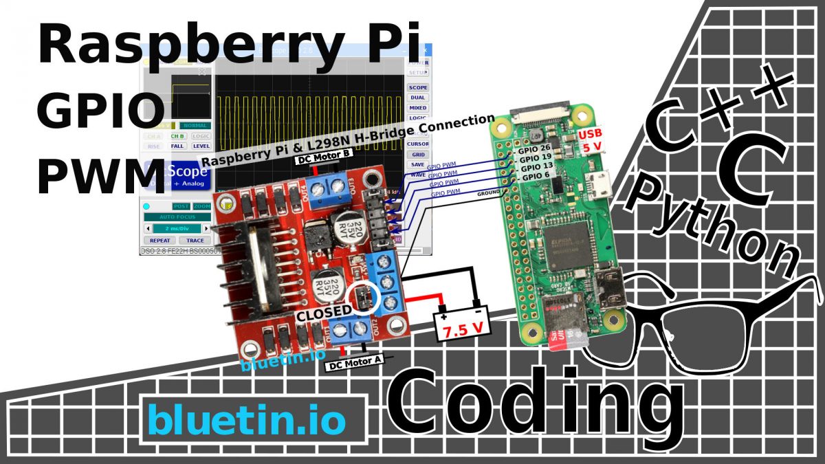
The Python code examples provided show how to set up PWM for two different H-Bridge configurations. The full H-Bridge wiring schematic is not included in this case since a full example schematic is shown above. For now, I am just focussing on the H-Bridge control logic.
A typical H-Bridge module I am using here is an L298N Dual H-Bridge DC motor driver module. You can get more information about this module here. This H-Bridge module is compatible with the Raspberry Pi, however, other L298N configurations might not be as compatible. There are other popular H-Bridge modules about but not all are compatible with the Raspberry Pi. So, test the electrical characteristics of any H-Bridge module before connecting to the Raspberry Pi.
The L298N H-Bridge module, like in the image below, has two connection configurations available. Which connection configuration you choose will depend largely on the number of PWM channels you want to use. The Raspberry Pi, for example, can use GPIO PWM on any GPIO pin so only four pins require connection to the H-Bridge Module. However, a six wire connection scheme, including two PWM channels, is available.
GPIO PWM Four Wire H-Bridge
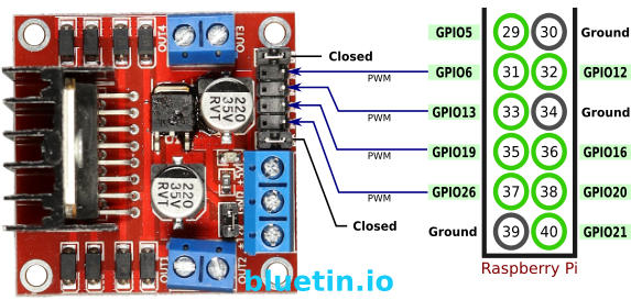
This wiring scheme is likely to be favourite because it only requires four GPIO pins on the Raspberry Pi. Furthermore, less code is required for each drive control GPIO pin transitions. However, with more efficient coding, the only real benefit between the four and the Six H-Bridge wire connections is the number of GPIO pins saved.
The H-Bridge Enable pins are closed so that the L298N direction control pins are always enabled. So, to drive DC motors, GPIO PWM is applied directly to the DC motor direction control pins. Review the code below for an example of how the four wire connection works.
#!/usr/bin/env python3

"""
File: skidsteer_four_pwm_test.py

This code will test Raspberry Pi GPIO PWM on four GPIO
pins. The code test ran with L298N H-Bridge driver module connected.

Website:	www.bluetin.io
Date:		27/11/2017
"""

__author__ = "Mark Heywood"
__version__ = "0.1.0"
__license__ = "MIT"

from gpiozero import PWMOutputDevice
from time import sleep

#///////////////// Define Motor Driver GPIO Pins /////////////////
# Motor A, Left Side GPIO CONSTANTS
PWM_FORWARD_LEFT_PIN = 26	# IN1 - Forward Drive
PWM_REVERSE_LEFT_PIN = 19	# IN2 - Reverse Drive
# Motor B, Right Side GPIO CONSTANTS
PWM_FORWARD_RIGHT_PIN = 13	# IN1 - Forward Drive
PWM_REVERSE_RIGHT_PIN = 6	# IN2 - Reverse Drive

# Initialise objects for H-Bridge PWM pins
# Set initial duty cycle to 0 and frequency to 1000
forwardLeft = PWMOutputDevice(PWM_FORWARD_LEFT_PIN, True, 0, 1000)
reverseLeft = PWMOutputDevice(PWM_REVERSE_LEFT_PIN, True, 0, 1000)

forwardRight = PWMOutputDevice(PWM_FORWARD_RIGHT_PIN, True, 0, 1000)
reverseRight = PWMOutputDevice(PWM_REVERSE_RIGHT_PIN, True, 0, 1000)


def allStop():
	forwardLeft.value = 0
	reverseLeft.value = 0
	forwardRight.value = 0
	reverseRight.value = 0

def forwardDrive():
	forwardLeft.value = 1.0
	reverseLeft.value = 0
	forwardRight.value = 1.0
	reverseRight.value = 0

def reverseDrive():
	forwardLeft.value = 0
	reverseLeft.value = 1.0
	forwardRight.value = 0
	reverseRight.value = 1.0

def spinLeft():
	forwardLeft.value = 0
	reverseLeft.value = 1.0
	forwardRight.value = 1.0
	reverseRight.value = 0

def SpinRight():
	forwardLeft.value = 1.0
	reverseLeft.value = 0
	forwardRight.value = 0
	reverseRight.value = 1.0

def forwardTurnLeft():
	forwardLeft.value = 0.2
	reverseLeft.value = 0
	forwardRight.value = 0.8
	reverseRight.value = 0

def forwardTurnRight():
	forwardLeft.value = 0.8
	reverseLeft.value = 0
	forwardRight.value = 0.2
	reverseRight.value = 0

def reverseTurnLeft():
	forwardLeft.value = 0
	reverseLeft.value = 0.2
	forwardRight.value = 0
	reverseRight.value = 0.8

def reverseTurnRight():
	forwardLeft.value = 0
	reverseLeft.value = 0.8
	forwardRight.value = 0
	reverseRight.value = 0.2

def main():
	allStop()
	forwardDrive()
	sleep(5)
	reverseDrive()
	sleep(5)
	spinLeft()
	sleep(5)
	SpinRight()
	sleep(5)
	forwardTurnLeft()
	sleep(5)
	forwardTurnRight()
	sleep(5)
	reverseTurnLeft()
	sleep(5)
	reverseTurnRight()
	sleep(5)
	allStop()


if __name__ == "__main__":
    """ This is executed when run from the command line """
    main()
GPIO PWM Six Wire H-Bridge
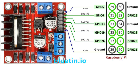
I use six wire H-Bridge connection for mostly the Arduino platform due to the limited number of PWM pins. In regards to the Raspberry Pi though, with software GPIO PWM, enough GPIO pins can be made PWM with consistent frequency. It is probably not necessary to use the six wire H-Bridge connection with the Raspberry Pi.
PWM is applied to the H-Bridge Enable pins and this will also add PWM to the DC motor direction control pins. The shunts are removed from the H-Bridge Enable pins before connecting to the Raspberry Pi. The Four H-Bridge DC motor direction control pins will now be pulled high or low depending on the motor direction required. So, review the Python code below to see how the six wire connection works.
#!/usr/bin/env python3

"""
File: skidsteer_two_pwm_test.py

This code will test Raspberry Pi GPIO PWM on four GPIO
pins. The code test ran with L298N H-Bridge driver module connected.

Website:	www.bluetin.io
Date:		27/11/2017
"""

__author__ = "Mark Heywood"
__version__ = "0.1.0"
__license__ = "MIT"

from gpiozero import PWMOutputDevice
from gpiozero import DigitalOutputDevice
from time import sleep

#///////////////// Define Motor Driver GPIO Pins /////////////////
# Motor A, Left Side GPIO CONSTANTS
PWM_DRIVE_LEFT = 21		# ENA - H-Bridge enable pin
FORWARD_LEFT_PIN = 26	# IN1 - Forward Drive
REVERSE_LEFT_PIN = 19	# IN2 - Reverse Drive
# Motor B, Right Side GPIO CONSTANTS
PWM_DRIVE_RIGHT = 5		# ENB - H-Bridge enable pin
FORWARD_RIGHT_PIN = 13	# IN1 - Forward Drive
REVERSE_RIGHT_PIN = 6	# IN2 - Reverse Drive

# Initialise objects for H-Bridge GPIO PWM pins
# Set initial duty cycle to 0 and frequency to 1000
driveLeft = PWMOutputDevice(PWM_DRIVE_LEFT, True, 0, 1000)
driveRight = PWMOutputDevice(PWM_DRIVE_RIGHT, True, 0, 1000)

# Initialise objects for H-Bridge digital GPIO pins
forwardLeft = PWMOutputDevice(FORWARD_LEFT_PIN)
reverseLeft = PWMOutputDevice(REVERSE_LEFT_PIN)
forwardRight = PWMOutputDevice(FORWARD_RIGHT_PIN)
reverseRight = PWMOutputDevice(REVERSE_RIGHT_PIN)

def allStop():
	forwardLeft.value = False
	reverseLeft.value = False
	forwardRight.value = False
	reverseRight.value = False
	driveLeft.value = 0
	driveRight.value = 0

def forwardDrive():
	forwardLeft.value = True
	reverseLeft.value = False
	forwardRight.value = True
	reverseRight.value = False
	driveLeft.value = 1.0
	driveRight.value = 1.0

def reverseDrive():
	forwardLeft.value = False
	reverseLeft.value = True
	forwardRight.value = False
	reverseRight.value = True
	driveLeft.value = 1.0
	driveRight.value = 1.0

def spinLeft():
	forwardLeft.value = False
	reverseLeft.value = True
	forwardRight.value = True
	reverseRight.value = False
	driveLeft.value = 1.0
	driveRight.value = 1.0

def SpinRight():
	forwardLeft.value = True
	reverseLeft.value = False
	forwardRight.value = False
	reverseRight.value = True
	driveLeft.value = 1.0
	driveRight.value = 1.0

def forwardTurnLeft():
	forwardLeft.value = True
	reverseLeft.value = False
	forwardRight.value = True
	reverseRight.value = False
	driveLeft.value = 0.2
	driveRight.value = 0.8

def forwardTurnRight():
	forwardLeft.value = True
	reverseLeft.value = False
	forwardRight.value = True
	reverseRight.value = False
	driveLeft.value = 0.8
	driveRight.value = 0.2

def reverseTurnLeft():
	forwardLeft.value = False
	reverseLeft.value = True
	forwardRight.value = False
	reverseRight.value = True
	driveLeft.value = 0.2
	driveRight.value = 0.8

def reverseTurnRight():
	forwardLeft.value = False
	reverseLeft.value = True
	forwardRight.value = False
	reverseRight.value = True
	driveLeft.value = 0.8
	driveRight.value = 0.2

def main():
	allStop()
	forwardDrive()
	sleep(5)
	reverseDrive()
	sleep(5)
	spinLeft()
	sleep(5)
	SpinRight()
	sleep(5)
	forwardTurnLeft()
	sleep(5)
	forwardTurnRight()
	sleep(5)
	reverseTurnLeft()
	sleep(5)
	reverseTurnRight()
	sleep(5)
	allStop()


if __name__ == "__main__":
    """ This is executed when run from the command line """
    main()
Related Articles
Motor Driver for Raspberry Pi Robot using TB6612FNG – Link.
L298N H-Bridge DC Motor Driver Module Quick Start Guide – Link.
Buying Featured Items
The purchase price is going to vary greatly depending on how quickly you want the items. Therefore shop around checking out Amazon, Ebay, Adafruit and local electronic stores.
UK Searches:
UK Amazon:
- L298N Dual H-Bridge – Search
- Raspberry Pi – Search
- MicroSD Card – Search
- Raspberry Pi Compatible Wi-Fi Dongle – Search
US Searches:
US Amazon:
- L298N Dual H-Bridge – Search
- Raspberry Pi – Search
- MicroSD Card – Search
- Raspberry Pi Compatible Wi-Fi Dongle – Search
On Closing
I hope you find this article useful – GPIO PWM For Raspberry Pi H-Bridge DC Motor Control, please like and share.


One thought on “GPIO PWM For Raspberry Pi H-Bridge DC Motor Control”
Comments are closed.